Control in vector control asynchronous drive systems is relevant for transportation and lifting equipment, as well as for the feed drive of various machines.
The reason for this is that the vector control with double-loop speed and flux linkage control channels provides high accuracy and wide range of speed control, as well as high torques.
This article describes the experience in simulation of a system for slave of an asynchronous drive based on of REPEAT software using a commercially available motor MTKN 412-6.
Input data for model building
It is assumed that the load should rotate with the following frequency and acceleration:
- load angular speed is  ;
;
- load angular acceleration ![]() .
.
The drive is equipped with a gearbox, to begin with we assume that:
- gear ratio is ![]() ;
;
- gearbox efficiency ![]()
It is also assumed that the motor is needed to drive heavy loads:
- static load resistance moment is Ml = 10000 N ∙ m;
- load inertia moment is ![]()
1. Calculation of power and selection of asynchronous electric motor
Based on the required parameters listed below, calculations are carried out to select a DC motor and its dynamic model.
- required load angular speed is ![]()
- required angular acceleration of the load is ![]()
- load inertia moment is ![]()
- load static resistance torque is ![]() ;
;
- gearbox efficiency is ![]() .
.
1) Operating angular rotation frequency of load
![]()
2) Let's estimate an approximate power of asynchronous motor using the formula
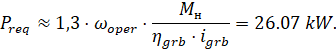
Given the required power, let’s choose a short-circuited rotor asynchronous motor MTKN 412-6. Reference data are listed in Table 1 below:
Table 1. Specifications of motor MTKN 412-6.
|
Capacity
Prat, kW |
Synchronous rotation frequency n0, rpm |
Rated load |
||
|
rotation frequency
nl, rpm |
EFC
ηl, % |
cosφl |
||
|
30 |
1000 |
945 |
87,5 |
0,85 |
|
Мrat, N·m |
Istrt, А |
Jmot, kg· |
||
|
303 |
820 |
0,63 |
||
1.1 Motor design parameters
1. Synchronous angular frequency of motor rotation
![]()
2. Rated motor speed
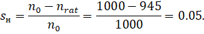
![]()
3. Rated motor slip
4. Rated stator current
![]()
1.2 Speed and torque requirements check
Calculate the new gear ratio using the formula
![]()
A chosen EM is checked for compliance with speed requirements.
Let’s check a chosen EM for compliance with speed requirements
![]()
![]()
The speed requirements are met.
A chosen EM is checked for compliance with torque requirements.

The permissible torque is
![]() ,
,
Then
![]()
The condition for torque conformity is met.
2. Determining of parameters of motor equivalent circuit based on motor specifications
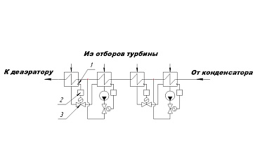
The reference data for the parameters is given in Table 2 below for the circuit in Figure 1:
Table 2. Parameters of asynchronous motor equivalent circuit
|
|
|
|
|
|
|
|
|
|
|
0,219 |
0,169 |
|
0,214 |
0,229 |
|
6,082 |
0,403 |
|
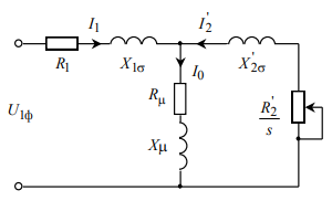
Figure 1. Asynchronous motor equivalent circuit
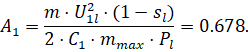
Motor stator current at fractional load
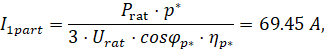
where ![]() - is a motor load factor, we take
- is a motor load factor, we take ![]()
![]() - is a motor load factor, we take
- is a motor load factor, we take ![]()
Power factor at fractional load:
![]()
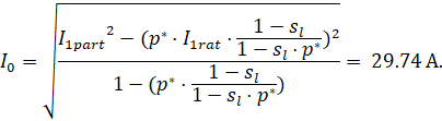
Let’s now determine the no-load current of asynchronous motor:
Then, in order to determine the active resistance of the rotor winding reduced to the stator winding, it is necessary to determine the critical slip, factors ![]() and
and ![]() (factors determining the AM design features).
(factors determining the AM design features).
Critical slip:
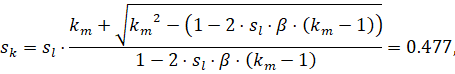
where ![]() – is a factor, the value of which is in the range from 0.6 to 2.5, we take
– is a factor, the value of which is in the range from 0.6 to 2.5, we take ![]() = 1.
= 1.
Factors:
![]()
Active resistance of rotor winding reduced to AM stator winding:
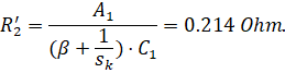
Active resistance of stator winding:
![]()
Then let’s determine the inductive resistances. First, it is necessary to determine the factor γ, which helps to determine the SC inductive impedance: ![]() с помощью которого определяется индуктивное сопротивление КЗ:
с помощью которого определяется индуктивное сопротивление КЗ:
then
![]()
Inductive resistance of stator winding:
![]()
The stator winding inductance due to stray flux, in rated operating conditions:
![]()
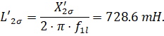
Calculate the rotor winding inductive resistance, reduced to the stator winding:
![]()
The rotor winding inductance due to stray flux:
According to the vector diagram, EMF of the magnetizing branch E1, induced by the air gap flux in the stator winding in rated operating mode is:
![]()
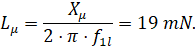
Inductive resistance of the magnetizing loop:
![]()
Resulting inductance:
3. Selecting of frequency transducer
Next, we select a frequency converter, an important element of the drive system power channel. For this system, we select frequency transducer Dyna-Hoist V (vector) 55 F 34-A. Reference parameter data is given in Table 3below:
Table 3. Parameters of frequency transducer
|
Parameters of supply system |
Output frequency |
Output current |
||
|
|
|
|
|
|
|
380-500 |
50/60 |
0-120 |
150 |
225 |
Conditions for checking the correctness of the frequency transducer are set relative to the electromechanical characteristics of the open-loop drive system, using which the maximum stator current is determined. Let’s simplify and take the permissible stator current as equal to:
![]()
Conditions for checking the correctness of frequency transducer selection:
![]()
![]()
![]()
![]()
The requirements are met, a suitable frequency transducer was selected.
4. Drive power channel
A structural diagram of the power channel of a continuous linearized FT-AM system in the rotating coordinate system, oriented by the resultant vector of rotor flux linkage is given in Figure 2. DC voltages are control signals at the input of the transducer of the power channel circuit diagram. The transducer output voltages are components of the stator voltage ![]() and
and ![]() in the orthogonal coordinate system d, q, oriented by the resultant vector of rotor flux linkage
in the orthogonal coordinate system d, q, oriented by the resultant vector of rotor flux linkage ![]() .
.
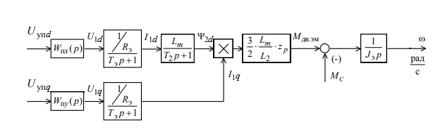
Figure 2. Structural diagram of FT-AM system power channel in the rotating two-phase coordinate system oriented by the resultant vector of rotor flux linkage
4.1. Calculation of parameters of elements of structural diagram of electric drive power channel
4.1.1 Calculation of motor parameters
Equivalent inductances of the windings:
- stator:
![]()
- rotor:
![]()
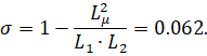
Dissipation factor:
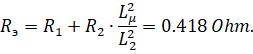
Equivalent resistance:
Electromagnetic time constants:
![]()
Rated motor flux:
![]()
Rated current value ![]() , А:
, А:
![]()
Rated current value ![]() , А:
, А:
![]()
Maximum allowable current value ![]() , А:
, А:
![]()
4.1.2 Calculation of transducer parameters
Maximum value of transducer gain:
where ![]() is the maximum value of control voltage, V. It is taken as equal to 10 V.
is the maximum value of control voltage, V. It is taken as equal to 10 V.
Transducer equivalent time constant
where ![]() is the transducer carrier frequency, Hz. Taken as equal to 8 kHz.
is the transducer carrier frequency, Hz. Taken as equal to 8 kHz.
5. Linearized ACS of frequency-controlled asynchronous drive with vector speed control
A structural diagram of a linearized continuous ACS of a frequency-controlled electric drive with vector control is shown in Figure 3.
The diagram uses the following designations:
![]() ,
, ![]() ,
, ![]() transfer functions of current, flux linkage and speed controllers;
transfer functions of current, flux linkage and speed controllers;
![]() current feedback factor,
current feedback factor, ![]() ;
;
![]() rotor flux linkage feedback factor,
rotor flux linkage feedback factor, ![]() ;
;
![]() rotor flux linkage feedback factor,
rotor flux linkage feedback factor, ![]() ;
;
Малая постоянная времени цепи обратной связи по току
![]()
где ![]() is the current measurement smoothing interval, where
is the current measurement smoothing interval, where ![]() is the accepted number of periods of frequency quantization in the current measurement interval.
is the accepted number of periods of frequency quantization in the current measurement interval.
Small time constant of flux linkage feedback loop
![]()
где ![]() is the interval of flux linkage calculation, where
is the interval of flux linkage calculation, where ![]() is the accepted number of frequency quantization periods in the interval of flux linkage calculation.
is the accepted number of frequency quantization periods in the interval of flux linkage calculation.
The small time constant of speed feedback loop with is calculated similarly with ![]() .
.
![]()
![]()
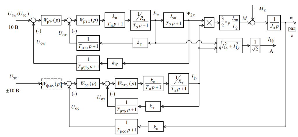
Figure 3. Structural diagram of linearized ACS of frequency-controlled asynchronous drive with vector speed control
5.1 Adjusting of flux linkage loop (FLL)
When streamlining the flux linkage loop, the internal optimized closed flux linkage loop is also represented by a truncated transfer function of order 1
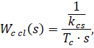
where ![]() is an equivalent time constant of the optimized current loop.
is an equivalent time constant of the optimized current loop.
The structural diagram of the flux linkage loop and the loop dynamic model built in REPEAT platform is given below in Figure 4 and Figure 5
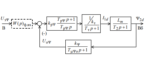
Figure 4. The structural diagram of the flux linkage loop
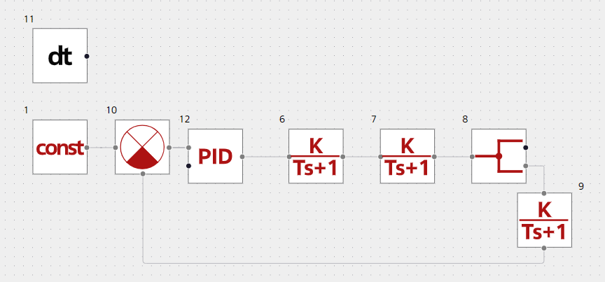
Figure 5. Diagram of dynamic model of the flux linkage loop
The flux linkage loop is characterized by one large time constant in direct channel ![]() and small time constants in direct channel
and small time constants in direct channel ![]() and in the feedback loop
and in the feedback loop ![]() .
.
A PI controller with a transfer function is taken as a flux linkage controller:
![]()
and tuned to the modulo optimum:
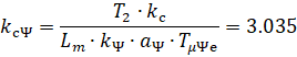
![]()
where ![]() is the equivalent small time constant of the flux linkage loop:
is the equivalent small time constant of the flux linkage loop:
![]()
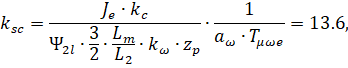
![]() current feedback factor:
current feedback factor:
![]()
where ![]() is the maximum value of the FLL input reference voltage;
is the maximum value of the FLL input reference voltage;
![]() optimization factor of the flux linkage loop
optimization factor of the flux linkage loop
5.1.1 Analysis of FLL transient
A reference stimulus transient of FLL is built. A value of FLL reference stimulus is ![]() = 10 V (see Figure 6).
= 10 V (see Figure 6).
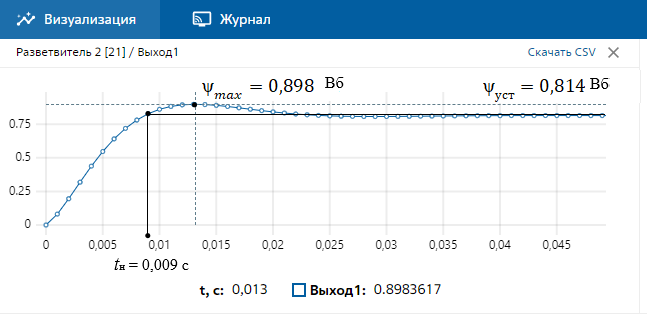
Figure 6. Reference stimulus transient of the flux linkage loop
Maximum deviation of ED flux linkage ![]() Wb steady-state value
Wb steady-state value ![]() Wb.
Wb.
Expected value of overshooting σ when tuning to the modulo optimum ![]() when tuning to the modulo optimum
when tuning to the modulo optimum ![]()
Overshoot σfll:
![]()
The deviation from the expected value is ![]() and is taken as permissible.
and is taken as permissible.
Buildup time of the resulting characteristic ![]() :
:
![]()
Calculated value ![]() :
:
![]()
Deviation of the measured and calculated value ![]() :
:
![]()
Deviation on ![]() is permissible. Adjustment of the flux linkage loop to the optimum modulo was successful.
is permissible. Adjustment of the flux linkage loop to the optimum modulo was successful.
5.2 Adjusting of speed loop (SL)
When streamlining the speed loop, the internal optimized closed current loop is also represented by a truncated transfer function of order 1, as in the FLL:
where ![]() is an equivalent time constant of the optimized current loop.
is an equivalent time constant of the optimized current loop.
A structural diagram of the speed loop and a diagram of the loop dynamic model are shown in Figure 7 and Figure 8 below.
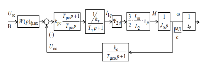
Figure 7. Speed loop structural diagram
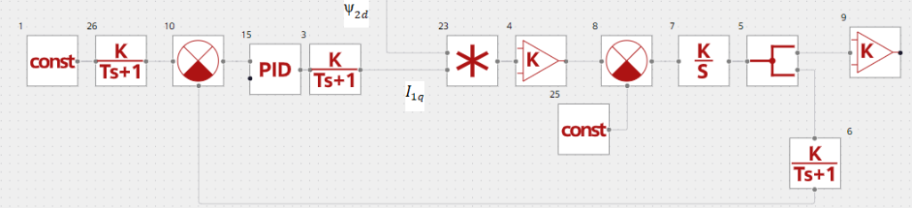
Figure 8. Diagram of speed loop dynamic model
As during vector control the EM electromagnetic torque is generated based on rotor flux linkage and stator current:
![]()
A complete diagram of the electric drive dynamic model looks as follows (see Figure 9):
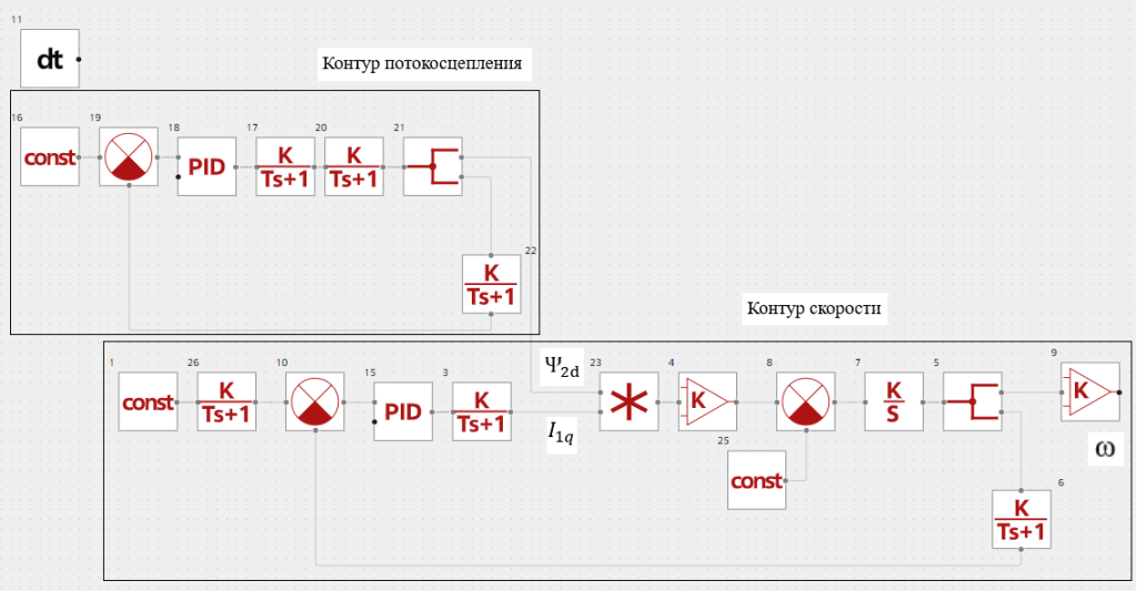
Figure 9. Diagram of dynamic model of linearized ACS of frequency-controlled asynchronous drive with speed vector control
PI controller with transfer function is taken as a speed controller:
![]()
and pre-tuned to the symmetric optimum:
![]()
where:
![]() equivalent small time constant of the speed loop:
equivalent small time constant of the speed loop:
![]()
![]() - current feedback factor:
- current feedback factor:
![]()
![]() maximum value of reference voltage at SL input;
maximum value of reference voltage at SL input;
![]() speed loop optimization factor.
speed loop optimization factor.
5.2.1 Analysis of SL transient
In order to analyze the SL transient we need to consider the following graph resulting from simulation using REPEAT software (see Figure 10):
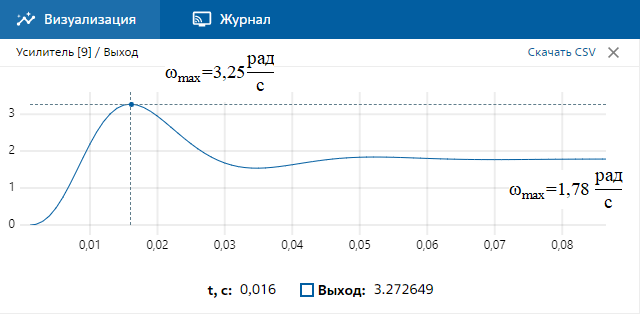
Figure 10. Reference stimulus transient of speed loop without inlet filter
The overshoot is
The overshoot is significant, which requires installation of an inlet filter. The following two smoothing filters with transfer functions should be installed:
![]()
where the time constant is chosen from the condition:
![]()
![]()
The optimized diagram of the speed loop dynamic model (see Figure 11) looks as follows:
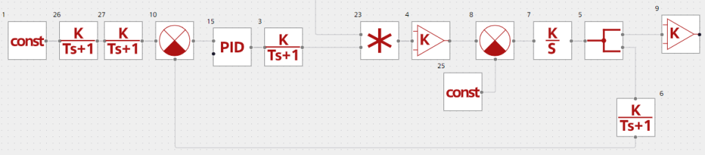
Figure 11. Diagram of dynamic model of speed loop with two inlet filters
The values of the optimized loop transient (see Figure 12) will improve significantly.
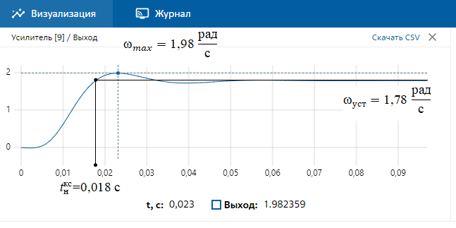
Figure 12. Reference stimulus transient of a speed loop with inlet filters
Adjusting of the speed loop with two inlet filters is close to adjusting to order 3 system MO. The speed loop is an order 1 astatic control system and provides accurate speed setpoint trial.
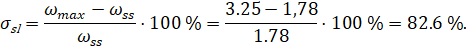
Overshoot σx:
![]()
The deviation from the expected value is ![]() and is adopted as permissible.
and is adopted as permissible.
Resulting characteristic buildup time ![]() :
:
![]()
Calculated value ![]() :
:
![]()
Deviation of the measured and calculated value ![]() :
:
![]()
The deviation of ![]() is permissible. Adjustment of the speed loop has been successful.
is permissible. Adjustment of the speed loop has been successful.
Simulation results
Based on these results it we can conclude that it is possible to build a dynamic model of asynchronous electric drive with vector control and to set the speed loop and flux linkage loop by synthesizing controllers and smoothing filters using REPEAT software. It can also help to analyze the circuit transients with determining the basic quality indicators such as overshoot and buildup time for series products such as short-circuited rotor asynchronous electric drive.