Highly demanded powerful industrial three-phase electric motors are huge, bulky and heavy devices. High quality simulation of transients of such devices is the most important condition for successful design of production facilities.
All this makes it possible to use these devices as efficiently as possible, and to avoid emergencies during operation. REPEAT software, a model-based design and simulation environment, is quite successful in accomplishing the tasks of creating digital models of electric motors. This article considers the approach to simulation and its results based on example of motor DAZO2-16-44-6/8U1 startup model, gives calculations of startup time characteristics and describes the cyclograms of parameters of this motor.
Input information for creating a model
The inputs and outputs of a single simulation unit are numbered from right to left (or from top to bottom). Correspondence of inputs and outputs to physical values and their units of measurement are given in Table 1.
Table 1. Data on asynchronous motor unit
|
Input/output No. |
Physical value |
UoM |
|
|
Input |
1 |
Supply voltage |
P.u. |
|
2 |
Resistance torque |
P.u. |
|
|
Output |
1 |
Frequency |
P.u. |
|
2 |
Shaft torque |
P.u. |
|
|
3 |
Rotor winding current |
P.u. |
|
It should be noted that the input voltage signal is converted to relative units automatically, ![]()
An image of AM unit is shown in Figure 1.
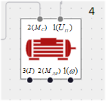
Figure 1. AM unit
A standard asynchronous electric motor (EM) DAZO2-16-44-6/8U1 (6 poles) was selected for simulation [1, p. 179]. Its parameters are given in Table 2. Calculation of the values required for simulation is given in the corresponding formulas.
Table 2. Parameters of DAZO2-16-44-6/8U1 (6 poles)
|
Type |
|
|
|
|
|
|
kW |
kV |
|
- |
||
|
DAZO2-16-44-6U1 |
400 |
6 |
991 |
0.84 |
|
|
|
Startup characteristics |
|
|||
|
% |
|
|
|
|
|
|
Rotor |
Permissible mechanism parameters |
||||
|
90.5 |
0.7 |
2.5 |
5.8 |
112.5 |
800 |
Calculations and model building
Rotational frequency of stator magnetic field:
![]()
Rated slip:
![]()
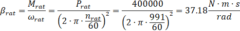
Stiffness of EM mechanical characteristic:
Mechanical time constant:
![]()
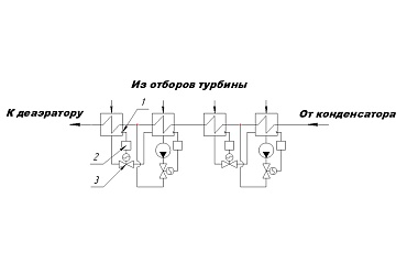
A study flow diagram for AM model assembled using REPEAT software is shown in Figure 2.
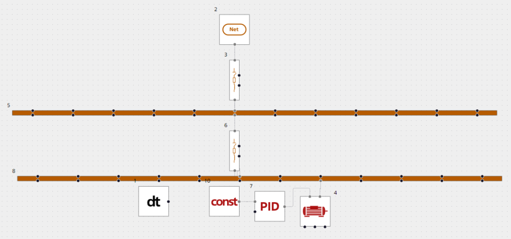
Figure 2. Study flow diagram for AM operation
As part of this study, the AM model was run. In order to simulate the resistance torque of the mechanism connected to the AM shaft, a PID controller unit described by the following equation was used:
![]()
Where ![]() . I.e., the PID controller works as an integrator of the constant signal
. I.e., the PID controller works as an integrator of the constant signal ![]() transmitted to its input. Thus, the time function of mechanism resistance torque is as follows:
transmitted to its input. Thus, the time function of mechanism resistance torque is as follows:
![]()
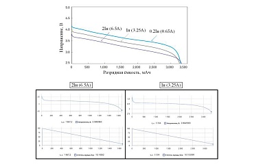
The dependences ![]() are shown in Figure 3, Figure 4 and Figure 5respectively.
are shown in Figure 3, Figure 4 and Figure 5respectively.
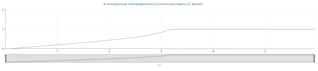
Figure 3. Dependence ![]() when starting AM
when starting AM
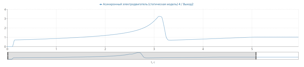
Figure 4. Dependence ![]() when starting AM
when starting AM
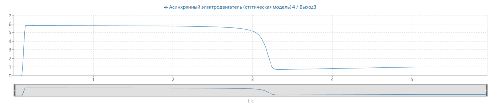
Figure 5. Dependence ![]() when starting AM
when starting AM
Results of simulation of asynchronous motor DAZO2-16-44-6/8U1
All output values have reached rated values. The startup time was . Based on the analysis of resulting values, we can conclude that the startup of the motor based on AM model designed using REPEAT software was successful. This result allows to use REPEAT software for high quality simulation of transients in industrial three-phase asynchronous motors and to recommend this software for industrial use.
References
- B.N. Neklepaev, I.P. Kryuchkov Electrical part of power plants and substations: Reference materials for term and graduation project design: Textbook for universities. – 4th edition, revised and supplemented. – М.: Energoatomizdat, 1989. – 608 p.: ill.