Mathematical modeling (MM) plays an important role in the modern world, being applied in various fields of science and engineering: from medicine to electric power industry. The efficiency of MM application depends largely on the calculations accuracy and on the software system performing them.
There are many different MM software systems. They can be designed both for specific professional calculations and for more general ones. The latter includes REPEAT software, which allows to simulate electrical as well as mechanical and thermal processes.
The purpose of this article is to evaluate the capabilities of REPEAT software in the electromechanical transient simulation.
Introduction to model building
To assess the capabilities of REPEAT software in simulation of electromechanical transients, a model of a power system including thermal (TPP) and hydroelectric (HPP) plants, power lines (PLs), power transformers (PTs), and static active load and dynamic motor load (SAL and DML) was designed.
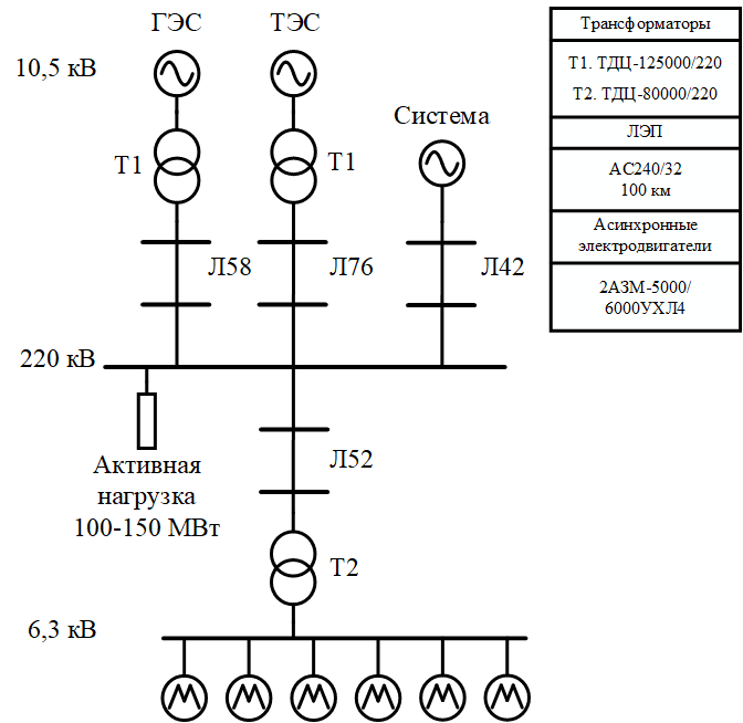
Figure 1. Structural diagram of simulated system
The study examines a transient (Tr) when SAL changes from 100 MW to 150 MW. A structural diagram of the model is shown in Figure 1. This model, built in REPEAT software, is presented in Appendix 1..
Calculation and model building
In REPEAT software, power generators are simulated by the “Controlled generator” block, the output signal of which is a voltage sine wave with its parameters - amplitude, frequency and phase - being controllable and able to be changed by sending of a corresponding signal to the generator model input. Thus, it is possible to use models of automatic excitation control system (AAC) to control the voltage amplitude, as well as models of thermal and hydraulic turbines, which include automatic rotation frequency control systems. Within the framework of this article, voltage amplitudes of generators were taken as constants, only models of equivalent TPP and HPP turbines were examined.
Structural diagrams of TPP and HPP turbine models are given in Figure 2.
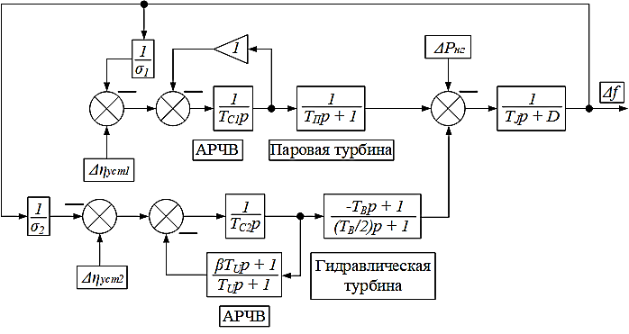
Figure 2. Structural diagrams of TPP and HPP turbine models
Parameters of these models are given in Table 1.
Table 1. Parameters of turbine models
|
|
|
|
|
|
|
|
nu |
- |
s |
s |
s |
- |
|
0.000 |
0.007 |
0.200 |
0.200 |
10.000 |
1.000 |
|
|
|
|
|
|
|
|
nu |
s |
- |
s |
s |
- |
|
0.000 |
7.000 |
5.000 |
5.000 |
2.000 |
2.000 |
Power lines in REPEAT are simulated in a simplified form, without taking into account capacitive susceptance [V.I. Idelchik Electrical systems and networks: a textbook for universities. – М.: Energoatomizdat, 1989. – 592 p.: ill.p.57], through the active and reactive resistance of PL.
PTs in REPEAT software are also simulated in a simplified form, without taking into account the processes in the magnetic circuit - through the active and reactive resistance of the reduced winding [1, p. 62].
Marking of the selected electrical equipment is given in Figure 1, reference data were taken from [2, p. 88] - power lines, [2, p. 248-249] - PT, [3, p. 201] - asynchronous electric motors.
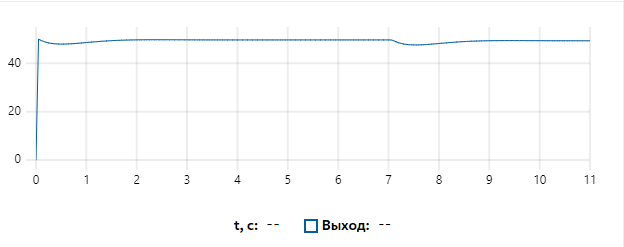
Figure 3. Frequency curve.
Tr in the system is induced by changing SAL from 100 MW to 150 MW in 7 s after the simulation start. The frequency curve is shown in Figure 3.
This curve can be subdivided into two sections: a startup section (0-3 s) and a SAL surge section (7-10 s). At each of these sections the ARFC systems perform their function and bring the frequency to a steady-state value.
The transients in DML are important. The curves of the angular speed of a rotor of one of the motors and the voltage in the DML connection point are shown in Figure 4 and Figure 5. It is worth noting that the angular speed is given in relative units from the rotation frequency of the magnetic field.
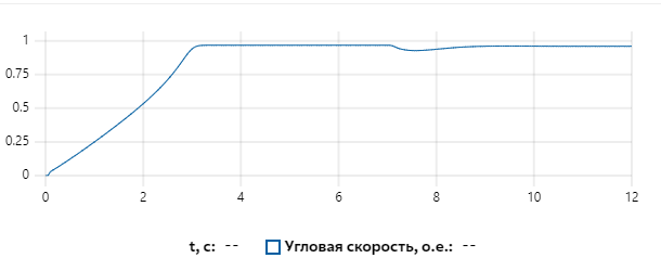
Figure 4. Angular speed of a rotor of one of the motors
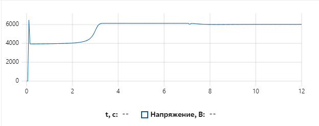
Figure 5. Voltage in the DML connection point
Based on Figure 4, the motors started successfully and the changes in SAL slightly increased the slip slowing down the rotor. Such a small effect is explained by the massiveness of the rotor with moment of inertia being equal to 135 ![]() . The voltage in the DML connection point increased as the motors started, and decreased slightly when SAL surged.
. The voltage in the DML connection point increased as the motors started, and decreased slightly when SAL surged.
The studied model also allows to consider power flows through TL. The number assigned to each line is indicated in Figure 1. The active and reactive power flow curves for each line are shown in Figures 6-13.
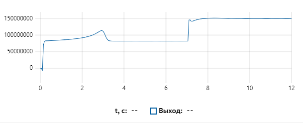
Figure 6. Active power flow through line 42
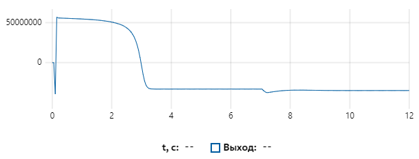
Figure 7. Reactive power flow through line 42
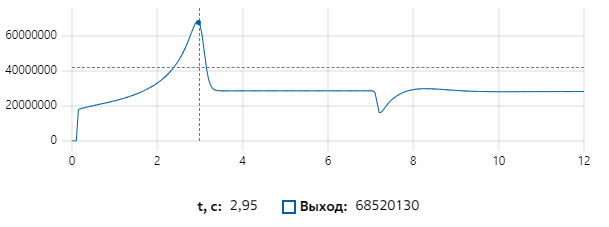
Figure 8. Active power flow through line 52
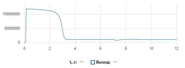
Figure 9. Reactive power flow through line 52
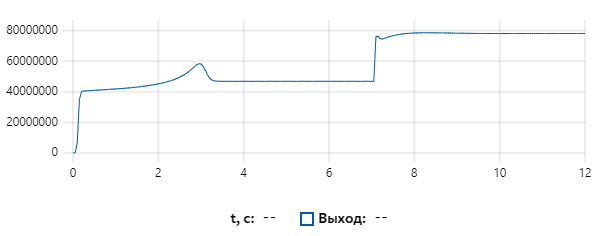
Figure 10. Active power flow through line 58
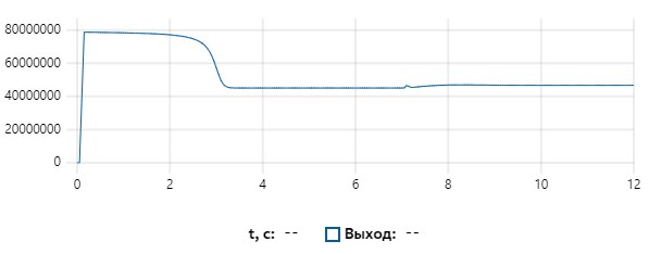
Figure 11. Reactive power flow through line 58
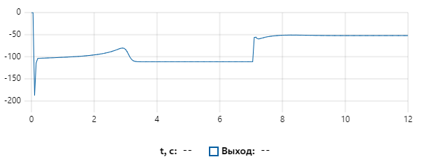
Figure 12. Active power flow through line 76
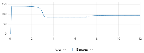
Figure 13. Reactive power flow through line 76
The currents through the load supply line are naturally high during the DML startup and decrease as the DML characteristics reach the steady state. A change in the system active load causes a natural change in the active power consumed by the pulse generator and a slight change in the reactive power. However, this Tr fades quite quickly as the ARFC systems act.
It is important to note that almost all the active power supply flows through lines 58 and 42. At the same time, the examined system is surplus in reactive power, consequently, its overflow through line 42 is negative – it is transferred to an external system. This is due to the absence of the studied model assumption – a constant generator voltage – so there is no reactive power control.
Simulation results
Based on the results, we can conclude that is possible to use REPEAT software to simulate electromechanical transients.
As part of the presented work, a study of electromechanical transient in the power system with mixed generation and combined load in REPEAT software was conducted. The results obtained are sufficiently reliable: the primary frequency control systems perform relevant functions, the distribution of power flows over the system is logically explainable, the impact of changes in the static load on the dynamic load is clearly seen.
Thus, it can be concluded that the REPEAT software is applicable in the field of simulation of real electromechanical transients in power engineering, when calculating modes in electrical networks.
References
-
V.I. Idelchik Electrical systems and networks: a textbook for universities. – М.: Energoatomizdat, 1989. – 592 p.: ill.
-
Handbook on design of power grids/ ed. by D. L. Faibisovich – 4th edition, revised and supplemented. – М.: ENAS, 2012. – 376 p.: ill.
-
B.N. Neklepaev, I.P. Kryuchkov Electrical part of power plants and substations: Reference materials for term and graduation project design: Textbook for universities. – 4th edition, revised and supplemented. – М.: Energoatomizdat, 1989. – 608 p.: ill.
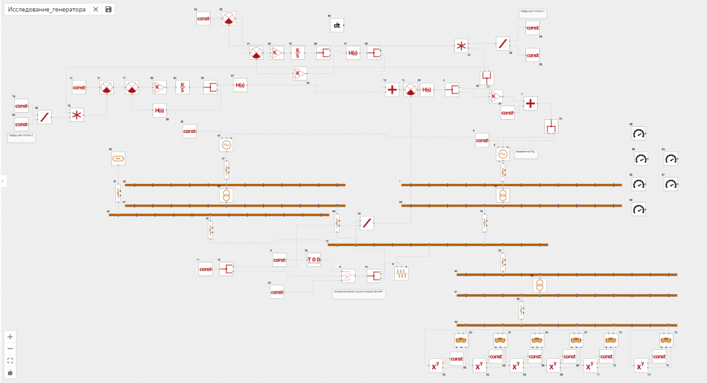
Appendix 1.
Model of the studied system built in REPEAT software